Making Graphene from Scratch
This was one of my all time favourite projects. In my open ended lab course, MATLS 2H04 back when I was a second year undergraduate student we had the entire semester to
"Measure the resistivity of a material and how it changes with temperature"
Naturally I overcomplicated the crap out of the problem statement and took it upon myself and our group to make a really complicated material. With total free reign, I decided to make graphene.
Yes, of that graphene fame. From scratch. As a group of 19 year olds. With minimal supervision.
Synthesis


The actual procedure is two-fold. First you take some graphite (like pencil lead, but cleaner ideally) and you oxidize it, then you make a shape with the graphite oxide, in our case we wanted it as a thin film. It then can be reduced back down to graphite and if its thin enough, it will be graphene (or monolayer graphite).
I'm sure you're thinking there, "but wait, graphite is the most stable allotrope of carbon, it cannot be oxidized in solid form". That is correct, it is the most stable allotrope of carbon, and it does have an oxide of the form CO or CO2 as in carbon monoxide gas or carbon dioxide gas typically. But it can have a partially oxidized unstable form as well which is a very very unique and interesting compound. This is what I chose to create. And as you can imagine it is not trivial to make something that would prefer not to exist (ie. thermodynamically unfavorable).
The procedure starts by making a strong oxidizer compound. One of the strongest actually, manganic acid. Its chemical formula is Mn2O7 and Mn is heptavalent meaning it has 7 unpaired electrons. It is created by adding a very strong oxidizer (potassium permanganate) to a very strong reducer (sulfuric acid). The two were added dropwise to each other and in an ice bath.

I would like to remind you I have specialization in chemistry, a full minor. Now. As a graduate. At the time, being in second year, my chemistry knowledge was indeed limited. What I was good at though was following instruction. I followed the procedure to a T and I read the MSDS of the chemicals and I was very careful. Nothing bad happened in this reaction. However when I look back at what I was doing, I blindly followed cautions like "remember, don't heat it above 55 C, keep at at 50 C". Well what could go wrong if it goes up 5 C when you're adding exothermic (gives off heat) chemicals to the beaker?
It detonates, explosively. Glass, sulfuric acid, fire everywhere.
Was I aware of this at the time? Kind of? I knew the reaction would fail so I was meticulous, but I didn't know it would fail because I would be dead.
C'est la vie.
So once you have the manganic acid, a few more chemicals are added (the full procedure was the Improved Hummers Method, check it out if you want to reproduce it), and graphite was added to the mixture. After reacting, the graphite oxide was filtered out sequentially with a variety of solvents and different separation techniques.
With the graphite oxide filtered and dried, it was added to purified water and it was ready for drop-casting. Drop-casting is a synthesis technique where you drop a drop of liquid on a substrate and allow it to dry, leaving the particles remaining. This can be observed when you drop a drop of coffee on your table and after it dries you have a thin film of dried coffee remaining on the table.
What I then needed was an environment free from vibrations, dust, and disturbances where my films can dry. Certainly not in an undergraduate lab ;) So I made an impromptu clean-room box in my bedroom, seen below.

Making Graphene Oxide Films
I tried drying the graphite oxide films on a variety of substrates. PET plastic, aluminum and glass (silica). I learned all about hydrophobicity and wetting angles and all sorts of good stuff.
Since this was all a learning experience, I tried a few ways to vibrate the mixture and make a consistent homogeneous mixture of graphene oxide particles suspended in the solvent (this is also called a colloid or suspension). I recalled the concept of resonance and standing waves and its ability to vibrate mixtures.
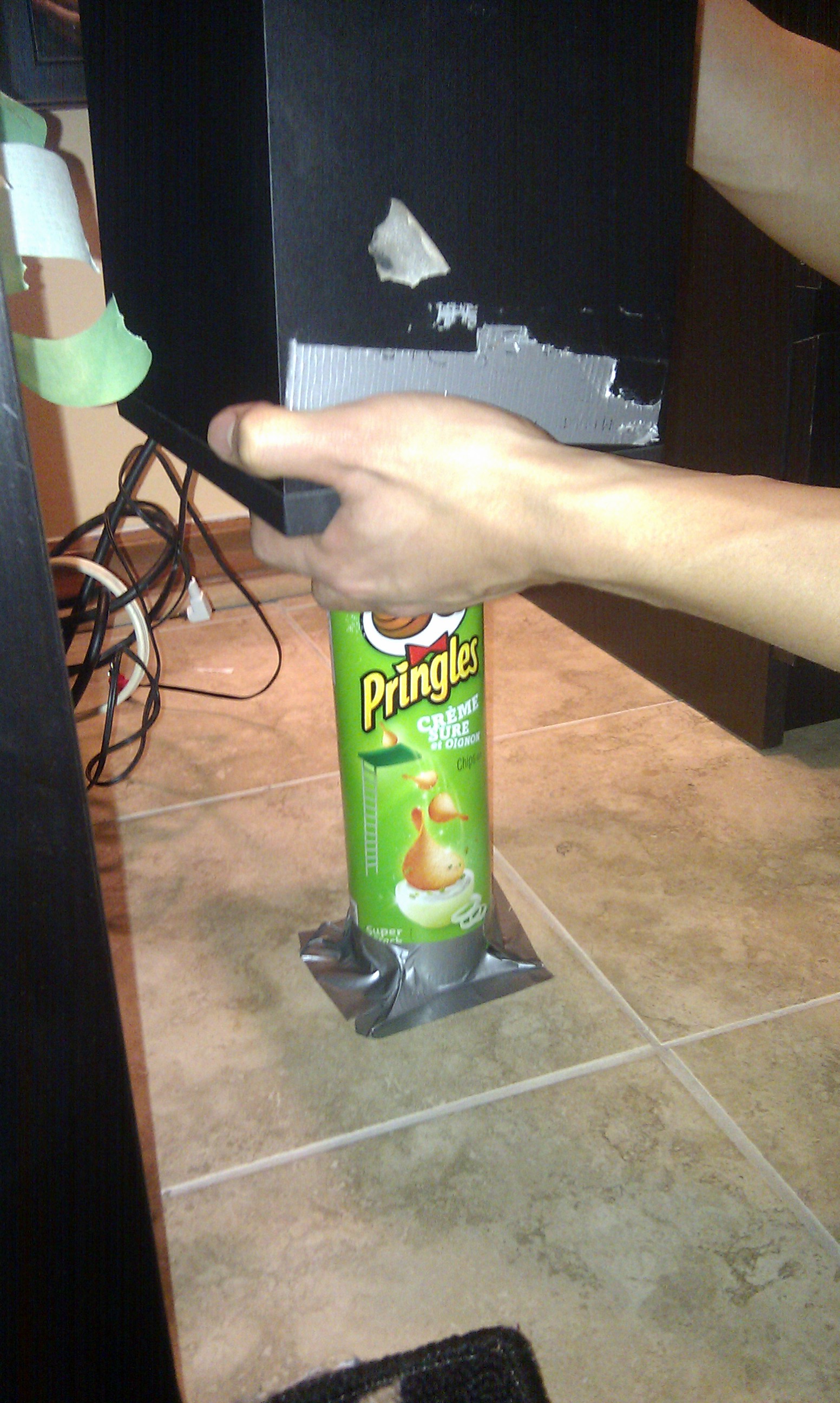
I constructed a Pringles can resonator, calculated the resonant frequency of the tube, got my sub-woofer and played the corresponding frequency to achieve standing waves. It worked, kinda. Most of the mixture happened at the surface, not down below. It was great to see the effects of resonance and standing waves applied to this problem, I had a lot of fun doing this.
Little did I know, I was entirely reinventing the wheel. There is already a commonly used device to agitate mixtures, an ultrasonicator. Ah well.
I eventually figured out I needed to use the ultrasonicator in my lab, vibrate my mixture to finely disperse the colloid, run run run back home, and drop-cast on silica microscope cover slide plates in my room. See the film below. The left is the reduced form, and the right is the unreduced form. There is a blob of sticky tack behind the semi-transparent graphene oxide.

(left) Reduced Graphene oxide. (right) graphene oxide
Synthesis of Reduced Graphene Oxide
Okay, I will be honest, I first heard of this graphene oxide -> reduced grapene oxide thing from a paper titled Laser Scribed Graphene. These scientists out of UCLA thinks they made a low-cost facile way to synthesize graphene in a wide variety of shapes fairly easily. Have you ever used those LightScribe CD burners from way back when? They were able to to use the laser from the CD burner on the surface of the CD and etch patterns in them. For example look at this one below:
LightScribe DVD Burner Reduction

The idea was then coating the surface of the CD with a film of PET plastic which is coated in graphene oxide. You could create the shape you want using the LightScribe software and it would etch the design into the surface of the CD.
So I tried this. Many times. I bought an external LightScribe CD burner and LightScribe CD and it did not work. I to this day don't know what I was doing wrong. Maybe the graphene oxide was too thick, or the laser was too weak. I followed the procedure to a T from the paper and I could not reproduce their results.
Naturally I did the next best thing. Maybe I need a bigger laser?
Bigger Laser
I contacted Prof. John Preston of the Engineering Physics department at McMaster. Dr. Preston studies nanomaterials and photonics. Naturally a perfect fit. I told him about the problem and asked him if I could use his KrF laser. He was very enthusiastic and very supportive and took us under his wing showing us the ropes. He recommended we try to measure the resistivity while we reduce it. So we needed electrical contacts on the film.
Sputtering is a method of vaporizing a material, and depositing it onto another material in a controlled uniform process. In our case we vaporized gold in an argon plasma and deposited it onto microscope cover slides in four lines. We needed four contact points because we used a four-point probe technique to measure the resistance with high accuracy. I will touch on 4-P probe afterwards.


So the procedure was done in three steps. Take a cleaned microscope cover slide, put a mask over it (such as Al foil) such that only four lines will be deposited onto the slide. Next contact leads were soldered onto the gold lines. Then graphene oxide was drop-casted onto the substrate and dried.
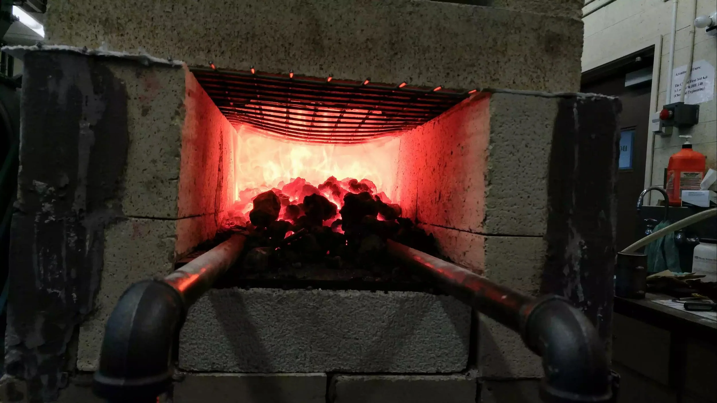
Okay now comes the fun bit! Hitting it with a laser. I don't have any good pictures of the laser unfortunately. So you will have to be satisfied with the following.

That small black hole at the back is where the laser comes out of. Yes not very impressive. Unfortunately I do not have video of the reduction. It was all quite stressful at the time.
Long story short, we were not able to measure the resistivity during reduction. Something quite peculiar happened that I have not been able to explain. When the laser would hit the graphene oxide, we would measure the current as a response using the 4 point probe technique. 4P is a technique where we apply a voltage across the two most outer lines. We measure the current between the two inner lines. This negates the internal resistance of the measuring apparatus and is used to very accurately measure the resistance of a material.
Using Ohm's law, we know the voltage we apply to the material is constant, the resistance is changing, and we measure the current. With the measured current we can calculate what the resistance should be. We expected if resistance was to go down, current must also scale linearly down. We did not observe this. We knew the resistance should be decreasing as oxygen functionalities get kicked off the lattice but what we observed was a fluctuating increasing current. It was impossible. Increasing current would mean the resistance was increasing, the material was getting more insulating.
Looking back now, nearly 5 years later, what I suspect is we created something similar to a dielectric? We had a conductor (gold), insulator (graphene oxide) and a conductor (growing surface reduced graphene oxide film). I am not sure what the properties are of this composite material when it gets struck by high energy photons. It may be possible for it to absorb some of the energy and get charged similar to a capacitor. If the material got charged and we are trying to delicately measure its current, we simply cannot. Again very peculiar. No idea.
We took these samples and further reduced them by thermal annealing on a hot plate. We tested the resistivity of samples reduced via lasers, and lasers+thermal. But not pure thermal (hey I was 19 okay, my methodology was not perfect).
Below is how the resistivity changed during thermal reduction. 4 samples were used and heated to each respective temperature and held for 1 minute. Please excuse my use of MS Excel...

Thickness of the films was measured using an Alphastep Stepper. The sample is scratched, then a stylus (similar to a record player) is brushed over the scratch and it measures the height differential.
The gold contact points in the above figure were done this way so resistivity could be measured using a different technique. The Van der Pauw method which can measure sheet resistance at liquid nitrogen temperatures. Below is what the apparatus looks like to plug it into the machine.

Conclusion
All in all, we ended up making our graphene. It was not monolayer, it ended up being around 1 micron thick which is many hundreds of sheets stuck on top of each other. But we managed to do it from scratch, following procedures in real papers. I considered quite an accomplishment at the time considering by that point I only had grade 12 Chemistry knowledge. It was my first introduction to nanomaterials and it set me down a path to study nanomaterials in my undergraduate. The work never really got any attention because it was unpublished and no one trusted a bunch of second year undergraduates, but I am still very proud of this work. I wish I would have pushed to get it published or to work on it in a summer term or something.